“Trusted Firmware-A移植”的版本间的差异
(→建立自己的平台) |
(→调整设备树电源配置) |
||
| 第225行: | 第225行: | ||
===调整设备树电源配置=== | ===调整设备树电源配置=== | ||
| + | 由于官方参考板DK1采用电源管理芯片做电源管理,而FS-MP1A采用分离电路作为电源管理,本例需要将文件中原有电源管理芯片相关内容去掉,增加上固定电源相关内容 | ||
| + | <ol> | ||
| + | <li>去掉原有电源管理内容</li> | ||
| + | |||
| + | DK1参考板电源管理芯片挂在I2C4上,而FS-MP1A并未使用I2C4总线,所以直接将I2C4相关内容完全删除即可。 | ||
| + | |||
| + | 修改fdts/stm32mp15xx-fsmp1x.dtsi文件 | ||
| + | |||
| + | 将文件中i2c4节点相关内容整体删除,删除内容如下: | ||
| + | <pre> | ||
| + | &i2c4 { | ||
| + | pinctrl-names = "default", "sleep"; | ||
| + | pinctrl-0 = <&i2c4_pins_a>; | ||
| + | pinctrl-1 = <&i2c4_pins_sleep_a>; | ||
| + | i2c-scl-rising-time-ns = <185>; | ||
| + | i2c-scl-falling-time-ns = <20>; | ||
| + | clock-frequency = <400000>; | ||
| + | status = " okay"; | ||
| + | secure-status = "okay"; | ||
| + | /*内容太长此处省略*/ | ||
| + | watchdog { | ||
| + | compatible = "st,stpmic1-wdt"; | ||
| + | status = "disabled"; | ||
| + | }; | ||
| + | }; | ||
| + | }; | ||
| + | </pre> | ||
| + | 修改fdts/stm32mp15xx-fsmp1x.dtsi文件,删除如下内容: | ||
| + | <pre> | ||
| + | &cpu0{ | ||
| + | cpu-supply = <&vddcore>; | ||
| + | }; | ||
| + | |||
| + | &cpu1{ | ||
| + | cpu-supply = <&vddcore>; | ||
| + | }; | ||
| + | </pre> | ||
| + | |||
| + | <li>添加固定电源配置</li> | ||
| + | |||
| + | 修改fdts/:文件 | ||
| + | |||
| + | 固定电源配置通常添加在根节点下,在根节点末尾位置添加如下内容(红色字体为需要添加的内容): | ||
| + | |||
| + | <div style="background-color:#F8F8F8;border:1px solid #E5E5E5;"> | ||
| + | vin: vin {<br> | ||
| + | :: compatible = "regulator-fixed";<br> | ||
| + | :: regulator-name = "vin";<br> | ||
| + | :: regulator-min-microvolt = <5000000>;<br> | ||
| + | :: regulator-max-microvolt = <5000000>;<br> | ||
| + | :: regulator-always-on;<br> | ||
| + | :};<br> | ||
| + | <font color="#FF0000"> | ||
| + | v3v3: regulator-3p3v {<br> | ||
| + | :: compatible = "regulator-fixed";<br> | ||
| + | :: regulator-name = "v3v3";<br> | ||
| + | :: regulator-min-microvolt = <3300000>;<br> | ||
| + | :: regulator-max-microvolt = <3300000>;<br> | ||
| + | :: regulator-always-on;<br> | ||
| + | :: regulator-boot-on;<br> | ||
| + | :};<br> | ||
| + | v1v8_audio: regulator-v1v8-audio {<br> | ||
| + | :: compatible = "regulator-fixed";<br> | ||
| + | :: regulator-name = "v1v8_audio";<br> | ||
| + | :: regulator-min-microvolt = <1800000>;<br> | ||
| + | :: regulator-max-microvolt = <1800000>;<br> | ||
| + | :: regulator-always-on;<br> | ||
| + | :: regulator-boot-on;<br> | ||
| + | :};<br> | ||
| + | v3v3_hdmi: regulator-v3v3-hdmi {<br> | ||
| + | ::compatible = "regulator-fixed";<br> | ||
| + | ::regulator-name = "v3v3_hdmi";<br> | ||
| + | ::regulator-min-microvolt = <3300000>;<br> | ||
| + | ::regulator-max-microvolt = <3300000>;<br> | ||
| + | ::regulator-always-on;<br> | ||
| + | ::regulator-boot-on;<br> | ||
| + | :};<br> | ||
| + | v1v2_hdmi: regulator-v1v2-hdmi {<br> | ||
| + | :: compatible = "regulator-fixed";<br> | ||
| + | :: regulator-name = "v1v2_hdmi";<br> | ||
| + | :: regulator-min-microvolt = <1200000>;<br> | ||
| + | :: regulator-max-microvolt = <1200000>;<br> | ||
| + | :: regulator-always-on;<br> | ||
| + | :: regulator-boot-on;<br> | ||
| + | :};<br> | ||
| + | vdd: regulator-vdd {<br> | ||
| + | :: compatible = "regulator-fixed";<br> | ||
| + | :: regulator-name = "vdd";<br> | ||
| + | :: regulator-min-microvolt = <3300000>;<br> | ||
| + | :: regulator-max-microvolt = <3300000>;<br> | ||
| + | :: regulator-always-on;<br> | ||
| + | :: regulator-boot-on;<br> | ||
| + | :};<br> | ||
| + | vdd_usb: regulator-vdd-usb {<br> | ||
| + | :: compatible = "regulator-fixed";<br> | ||
| + | :: regulator-name = "vdd_usb";<br> | ||
| + | :: regulator-min-microvolt = <3300000>;<br> | ||
| + | :: regulator-max-microvolt = <3300000>;<br> | ||
| + | :: regulator-always-on;<br> | ||
| + | :: regulator-boot-on;<br> | ||
| + | :};<br> | ||
| + | </font> | ||
| + | }; | ||
| + | </div> | ||
| + | |||
| + | <li>重新编译源码</li> | ||
| + | linux@ubuntu:$ make -f $PWD/../Makefile.sdk TFA_DEVICETREE=stm32mp157a-fsmp1a TF_A_CONFIG=trusted ELF_DEBUG_ENABLE='1' all | ||
| + | <li>烧写后启动</li> | ||
| + | |||
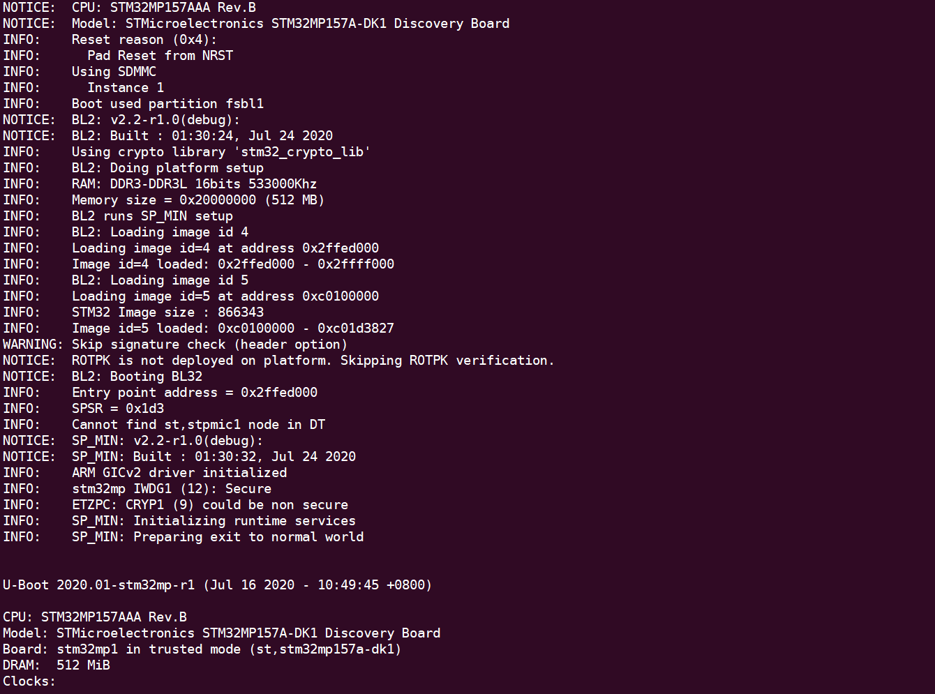
| + | 重新烧写后启动现象如下: | ||
| + | |||
| + | [[Image:39-4-4-1.png]]<br> | ||
| + | |||
| + | 可以看到现在已经可以启动到u-boot了 | ||
| + | |||
| + | </ol> | ||
| + | |||
===eMMC移植=== | ===eMMC移植=== | ||
2021年3月18日 (四) 13:58的版本
目录
Trusted Firmware-A简介
嵌入式高速发展的今天,大量的嵌入式设备使用了Arm为核心的芯片。我们会接触到越来越多的嵌入式设备,一个问题油然而生:数量如此巨大的嵌入式设备的安全性如何?目前针对嵌入式安全的技术和标准可谓千姿百态,除了必要的硬件安全技术,与之配套的安全软件也是必不可少的一部分。今天我们要介绍的是基于Arm 的可信固件Trusted Firmware-A,简称TF-A。它是一个开源软件,运行在一个硬件隔离的安全环境中并提供安全服务。
实验目的
完成TF-A的基本功能实现TF-A引导u-boot启动。
实验平台
华清远见开发环境,FS-MP1A平台
实验步骤
本实验基于tf-a-stm32mp-2.2版本,然后添加意法半导体提供的补丁文件。在意法半导体官方的tf-a中移植我们自己的tf-a。
导入源码
如果之前已经建立了源码目录,并且导入了源码包,即可跳过本小节。
建立源码目录
linux@ubuntu:$ cd ~
linux@ubuntu:$ mkdir FS-MP1A
将【华清远见-FS-MP1A开发资料\02-程序源码\04-Linux系统移植\01-官方源码】下的en.SOURCES-stm32mp1-openstlinux-5-4-dunfell-mp1-20-06-24.tar.xz压缩包,导入到ubuntu下的${HOME}/FS-MP1A目录下。
解压缩源码包
linux@ubuntu:$ tar xvf en.SOURCES-stm32mp1-openstlinux-5-4-dunfell-mp1-20-06-24.tar.xz
解压完成后得到“stm32mp1-openstlinux-5.4-dunfell-mp1-20-06-24”目录
进入tf-a目录下
inux@ubuntu:$ cd ~/FS-MP1A/stm32mp1-openstlinux-5.4-dunfell-mp1-20-06-24/sources/arm-ostl-linux-gnueabi/tf-a-stm32mp-2.2.r1-r0
该目录下以patch结尾的文件为ST官方提供的补丁文件;tf-a-stm32mp-2.2.r1-r0.tar.gz为标准tf-a源码包。
解压标准tf-a源码包
linux@ubuntu:$ tar -xvf tf-a-stm32mp-2.2.r1-r0.tar.gz
解压完成后得到tf-a-stm32mp-2.2.r1目录
进入tf-a源码目录下:
linux@ubuntu:$ cd tf-a-stm32mp-2.2.r1
将ST官方补丁文件打到tf-a源码中:
linux@ubuntu:$ for p in `ls -1 ../*.patch`; do patch -p1 < $p; done
TF卡分区
要对TF卡进行烧录,需要先将TF接入到ubuntu系统中。
查看TF卡分区
linux@ubuntu:$ ls /dev/sd*
由上图所示只有“/dev/sdb1”一个分区则需要重新进行分区。
首先删除原有分区
linux@ubuntu:$ sudo parted -s /dev/sdb mklabel msdos
如果显示如下内容,则表示设备已经被挂载,需要卸载掉设备再删除分区。
卸载设备
linux@ubuntu:$ umount /dev/sdb1
卸载完成后重新执行删除分区命令
linux@ubuntu:$ sudo parted -s /dev/sdb mklabel msdos
对tf进行重新分区
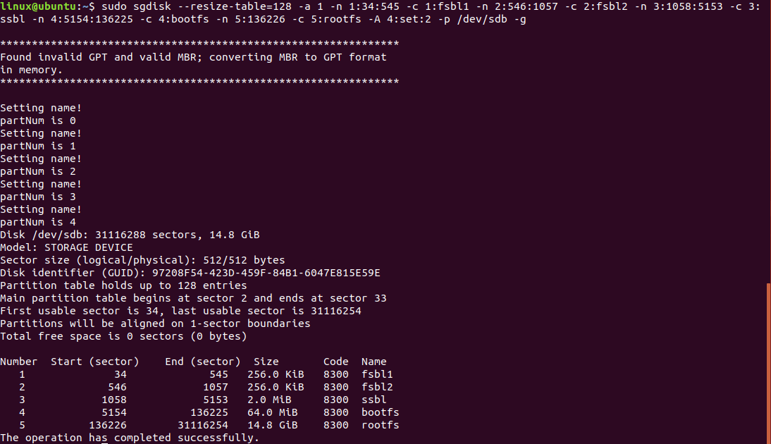
linux@ubuntu:$ sudo sgdisk --resize-table=128 -a 1 -n 1:34:545 -c 1:fsbl1 -n 2:546:1057 -c 2:fsbl2 -n 3:1058:5153 -c 3:ssbl -n 4:5154:136225 -c 4:bootfs -n 5:136226 -c 5:rootfs -A 4:set:2 -p /dev/sdb -g
注意:最后-p /dev/sdb参数中的/dev/sdb需要按照实际ubuntu中的tf节点为准,否则可能发生不可预料的后果。
建立自己的平台
- 配置工具链
- 增加板级相关文件
- 编译源码
- 固件烧写
- 启动开发板
导入交叉编译工具链(如果还未安装SDK可参考《SDK工具链安装》章节进行安装)
linux@ubuntu:$ source /opt/st/stm32mp1/3.1-openstlinux-5.4-dunfell-mp1-20-06-24/environment-setup-cortexa7t2hf-neon-vfpv4-ostl-linux-gnueabi
验证开发工具是否安装正确,显示版本信息如下图所示。
linux@ubuntu:$ $CC --version
进入到tf-a源码目录
linux@ubuntu:$ cd ~/FS-MP1A/stm32mp1-openstlinux-5.4-dunfell-mp1-20-06-24/sources/arm-ostl-linux-gnueabi/tf-a-stm32mp-2.2.r1-r0/tf-a-stm32mp-2.2.r1
添加设备树文件
linux@ubuntu:$ cp fdts/stm32mp15xx-dkx.dtsi  fdts/stm32mp15xx-fsmp1x.dtsi
linux@ubuntu:$ cp  fdts/stm32mp157a-dk1.dts  fdts/stm32mp157a-fsmp1a.dts
修改上层目录下的Makefile.sdk编译脚本在TFA_DEVICETREE配置项中添加stm32mp157a-fsmp1a
TFA_DEVICETREE ?= stm32mp157a-fsmp1a stm32mp157a-dk1 stm32mp157d-dk1 stm32mp157c-dk2 stm32mp157f-dk2 stm32mp157c-ed1 stm32mp157f-ed1 stm32mp157a-ev1 stm32mp157c-ev1 stm32mp157d-ev1 stm32mp157f-ev1
修改fdts/stm32mp157a-fsmp1a.dts将
#include "stm32mp15xx-dkx.dtsi"
修改为
#include "stm32mp15xx-fsmp1x.dtsi"
执行如下指令编译trusted:
linux@ubuntu:$ make -f $PWD/../Makefile.sdk TFA_DEVICETREE=stm32mp157a-fsmp1a TF_A_CONFIG=trusted ELF_DEBUG_ENABLE='1' all
编译成功后,最后显示内容(部分截图)如下:
编译完成后会在上级build/trusted目录得到如下文件:
linux@ubuntu:$ ls ../ build/trusted
linux@ubuntu:$ cd ../ build/trusted
由于在移植过程中会多次烧写固件并且会导致正常tf-a无法启动,因此推荐使用TF卡启动的方式来验证。
tf-a需要使用trusted 格式的u-boot镜像启动,具体的编译方法可参考《U-boot移植》章节中的“生成Trusted镜像”小节。
将TF接入ubuntu系统后,查看TF卡分区
linux@ubuntu:$ ls /dev/sd*
/dev/sdb为TF卡设备。如果该设备下只有/dev/sdb1一个分区则重新分区。
执行如下指令烧写u-boot:
linux@ubuntu:$ sudo dd if=tf-a-stm32mp157a-fsmp1a-trusted.stm32 of=/dev/sdb1 conv=fdatasync
linux@ubuntu:$ sudo dd if=tf-a-stm32mp157a-fsmp1a-trusted.stm32 of=/dev/sdb2 conv=fdatasync
linux@ubuntu:$ sudo dd if=u-boot-stm32mp157a-fsmp1a-trusted.stm32 of=/dev/sdb3 conv=fdatasync
其中前两条命令“tf-a-stm32mp157a-fsmp1a-trusted.stm32”为本章节编译得到的,第三条命令中的“u-boot-stm32mp157a-fsmp1a-trusted.stm32”则为《U-boot移植》章节中的“生成Trusted镜像”小节得到。
将拨码开关设置为SD卡启动方式:
| Boot mode | BOOT2 | BOOT1 | BOOT0 |
| Engineering boot | 1 | 0 | 0 |
| Forced USB bootfor flashing | 0 | 0 | 0 |
| eMMC | 0 | 1 | 0 |
| SDCARD | 1 | 0 | 1 |
将制作好的TF卡插入开发板,上电后会出现如下错误提示:
这个错误产生的原因是电源初始化错误,需重新调整电源相关配置
调整设备树电源配置
由于官方参考板DK1采用电源管理芯片做电源管理,而FS-MP1A采用分离电路作为电源管理,本例需要将文件中原有电源管理芯片相关内容去掉,增加上固定电源相关内容
- 去掉原有电源管理内容
- 添加固定电源配置
- compatible = "regulator-fixed";
- regulator-name = "vin";
- regulator-min-microvolt = <5000000>;
- regulator-max-microvolt = <5000000>;
- regulator-always-on;
- compatible = "regulator-fixed";
- };
- compatible = "regulator-fixed";
- regulator-name = "v3v3";
- regulator-min-microvolt = <3300000>;
- regulator-max-microvolt = <3300000>;
- regulator-always-on;
- regulator-boot-on;
- compatible = "regulator-fixed";
- };
- compatible = "regulator-fixed";
- regulator-name = "v1v8_audio";
- regulator-min-microvolt = <1800000>;
- regulator-max-microvolt = <1800000>;
- regulator-always-on;
- regulator-boot-on;
- compatible = "regulator-fixed";
- };
- compatible = "regulator-fixed";
- regulator-name = "v3v3_hdmi";
- regulator-min-microvolt = <3300000>;
- regulator-max-microvolt = <3300000>;
- regulator-always-on;
- regulator-boot-on;
- compatible = "regulator-fixed";
- };
- compatible = "regulator-fixed";
- regulator-name = "v1v2_hdmi";
- regulator-min-microvolt = <1200000>;
- regulator-max-microvolt = <1200000>;
- regulator-always-on;
- regulator-boot-on;
- compatible = "regulator-fixed";
- };
- compatible = "regulator-fixed";
- regulator-name = "vdd";
- regulator-min-microvolt = <3300000>;
- regulator-max-microvolt = <3300000>;
- regulator-always-on;
- regulator-boot-on;
- compatible = "regulator-fixed";
- };
- compatible = "regulator-fixed";
- regulator-name = "vdd_usb";
- regulator-min-microvolt = <3300000>;
- regulator-max-microvolt = <3300000>;
- regulator-always-on;
- regulator-boot-on;
- compatible = "regulator-fixed";
- };
- 重新编译源码
- 烧写后启动
DK1参考板电源管理芯片挂在I2C4上,而FS-MP1A并未使用I2C4总线,所以直接将I2C4相关内容完全删除即可。
修改fdts/stm32mp15xx-fsmp1x.dtsi文件
将文件中i2c4节点相关内容整体删除,删除内容如下:
&i2c4 {
	pinctrl-names = "default", "sleep";
	pinctrl-0 = <&i2c4_pins_a>;
	pinctrl-1 = <&i2c4_pins_sleep_a>;
	i2c-scl-rising-time-ns = <185>;
	i2c-scl-falling-time-ns = <20>;
	clock-frequency = <400000>;
	status = " okay";
secure-status = "okay";
	/*内容太长此处省略*/
		watchdog {
			compatible = "st,stpmic1-wdt";
			status = "disabled";
		};
	};
};
修改fdts/stm32mp15xx-fsmp1x.dtsi文件,删除如下内容:
&cpu0{
	cpu-supply = <&vddcore>;
};

&cpu1{
	cpu-supply = <&vddcore>;
};
修改fdts/:文件
固定电源配置通常添加在根节点下,在根节点末尾位置添加如下内容(红色字体为需要添加的内容):
vin: vin {
v3v3: regulator-3p3v {
v1v8_audio: regulator-v1v8-audio {
v3v3_hdmi: regulator-v3v3-hdmi {
v1v2_hdmi: regulator-v1v2-hdmi {
vdd: regulator-vdd {
vdd_usb: regulator-vdd-usb {
};
linux@ubuntu:$ make -f $PWD/../Makefile.sdk TFA_DEVICETREE=stm32mp157a-fsmp1a TF_A_CONFIG=trusted ELF_DEBUG_ENABLE='1' all
重新烧写后启动现象如下:
可以看到现在已经可以启动到u-boot了


